

Learn what causes five common op-amp problems, including output clipping, oscillation, overheating, current limiting and distortion. This guide explains how to identify each issue and provides practical steps to improve amplifier performance and reliability.
Operational amplifiers are used in everything from basic signal-conditioning circuits to high-voltage motion-control systems. Although op-amps are extremely versatile, unexpected behavior can occur when the amplifier’s limitations are overlooked.
An output that clips, oscillates, overheats, or fails to deliver the expected current does not necessarily indicate that the amplifier is defective. These problems are often caused by operating conditions that exceed one or more of the device’s specifications. This article examines five common op-amp problems, explains what causes them, and provides practical steps engineers can take to correct them.
1. The Output Signal is Clipping
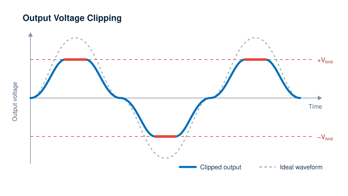
One of the most common op-amp problems occurs when the output signal stops increasing and appears flattened near the positive or negative supply rail. This behavior is known as clipping. An amplifier powered by ±50 V supplies cannot necessarily produce an output voltage of ±50 V. Internal components require a certain amount of voltage to operate correctly, preventing the output from reaching the supply rails.
The difference between the supply voltage and the maximum output voltage is known as output voltage headroom. As output current increases, the voltage dropped across the amplifier’s output stage typically increases as well. This means the maximum output voltage may decrease when the amplifier drives a heavier load.
For example, an amplifier operating from ±50 V supplies may only be able to produce ±45 V under a particular load condition. If the input signal requires an output of ±48 V, the amplifier will saturate and the waveform will clip.
How to Fix Output Clipping
Start by reviewing the amplifier’s output voltage swing datasheet spec. Pay close attention to the output current, supply voltage, and temperature conditions associated with the specification.
Depending on the application, clipping may be reduced by:
- Increasing the supply voltage without exceeding the amplifier’s maximum rating
- Reducing the required output voltage
- Reducing the output current
- Increasing the load impedance
- Selecting an amplifier with lower output headroom
- Using a bridge configuration to increase the voltage across the load
Always leave additional voltage margin for supply variation, temperature changes, component tolerances, and unexpected load conditions.
For a more detailed explanation, read our article: Why Doesn’t My Amplifier Reach the Supply Rails?.
2. The Amplifier is Oscillating or Ringing
An op-amp should reproduce the intended signal cleanly. If the output contains continuous oscillation, excessive overshoot, or ringing following a fast transition, the circuit may be unstable.
Op-amp stability depends on the relationship between the amplifier’s gain and the phase shift around its feedback loop. If the signal experiences enough phase shift while the loop still has sufficient gain, negative feedback can begin to behave like positive feedback. The result may be ringing or sustained oscillation. Capacitive loads are a frequent cause of instability. A load capacitance interacts with the amplifier’s output impedance and introduces an additional pole into the feedback response. This reduces phase margin and can push an otherwise stable circuit toward oscillation.
Piezoelectric actuators, long cables, semiconductor test equipment, and other capacitive loads can make this problem especially important in power amplifier applications. Circuit layout can also affect stability. Long traces, poor grounding, inadequate supply bypassing, and parasitic capacitance around the input and feedback nodes can all introduce unwanted behavior.
.png?width=1200&height=675&name=op-amp-oscillation-diagram%20(1).png)
How to Fix Op-amp Instability
The correct solution depends on the amplifier, circuit configuration, and load, but common approaches include:
- Adding a small isolation resistor between the amplifier output and the capacitive load
- Using an appropriate compensation network
- Increasing the circuit’s noise gain
- Selecting an amplifier designed to remain stable at the required closed-loop gain
- Placing supply bypass capacitors close to the amplifier
- Shortening sensitive input and feedback traces
- Separating high-current output paths from low-level input signals
- Following the layout recommendations in the product datasheet
An oscilloscope can help identify overshoot and ringing, but a Bode plot provides a more complete view of the circuit’s stability. Engineers should evaluate both gain margin and phase margin under the expected load conditions. Apex offers a free software tool, Power Design, to help plot these graphs for you.
3. The Amplifier is Overheating
Power op-amps can deliver substantial voltage and current to a load, but some of that power is also dissipated as heat inside the amplifier. Internal power dissipation is determined by the voltage remaining across the output stage and the current flowing through it. A simplified estimate at a particular operating point is:
Power Dissipation ≈ Voltage Across the Amplifier Output Stage × Output Current
Consider an amplifier operating from a +50 V supply and producing a +20 V output while delivering 2 A. Approximately 30 V remains across the amplifier’s output stage.
Power Dissipation ≈ 30 V × 2 A = 60 W
This simplified example does not include quiescent power or the complete signal cycle, but it demonstrates how an amplifier can dissipate considerable power even when the load receives the intended output. If heat cannot dissipate from the semiconductor junction quickly enough, the junction temperature will rise. Excessive junction temperature can cause changes in performance, activate thermal protection, reduce device lifetime, or permanently damage the device.
How to Fix an Overheating Op-amp
Begin by calculating the amplifier’s expected internal power dissipation under normal and worst-case conditions. Next, use the package’s thermal resistance to estimate junction temperature:
Junction Temperature = Ambient Temperature + (Power Dissipation × Thermal Resistance)
Depending on the package, the complete calculation may also include junction-to-case resistance, thermal washer resistance, heatsink resistance, and case-to-heatsink interface resistance.
Potential solutions include:
- Using a larger or more efficient heatsink
- Improving airflow
- Reducing the supply voltage
- Reducing the output current
- Lowering the ambient temperature
- Selecting a package with better thermal performance
- Using a PWM amplifier when system requirements allow
- Confirming that the operating load line remains inside the amplifier’s Safe Operating Area
Thermal calculations and Safe Operating Area analysis should both be completed. A sufficient heatsink does not make it safe to operate outside the device’s SOA.
To learn more, read our article: Safe Operating Area: How to Read SOA Curves and Improve Amplifier Reliability.
4. The Amplifier Cannot Deliver the Required Current
An op-amp may produce the expected voltage when no load is connected but fail as soon as the load begins drawing current. The output voltage may drop, distort, or stop increasing even though it remains far from the supply rails. This commonly occurs when the required output current exceeds the amplifier’s capability or activates its current-limiting circuitry. The required current can be estimated using the load impedance. For a resistive load:
Output Current = Output Voltage ÷ Load Resistance ( I = V / R)
A circuit delivering 20 V across a 5 Ω resistive load must supply 4 A.
Reactive loads require additional analysis. For a capacitive load driven by a changing voltage:
Current = Capacitance × Rate of Change in Voltage ( I = C * (dv / dt))
This relationship explains why a piezoelectric actuator may require a large amount of current during fast voltage transitions even if its average current appears relatively low. Motor windings, coils, and other inductive loads create their own challenges. Stored energy and back electromotive force can expose the amplifier to voltage and current conditions that are not obvious from the load’s DC resistance.
How to Fix Insufficient Output Current
Possible solutions include:
- Selecting an amplifier with a higher continuous and peak current rating
- Reducing the required output voltage
- Increasing the load impedance
- Reducing the signal frequency or transition speed
- Placing compatible amplifiers in parallel
- Confirming that current-limit components are correctly selected
- Adding appropriate protection for inductive loads
- Checking whether the amplifier is exceeding its SOA before reaching its published current rating
Remember that a device’s maximum voltage and maximum current ratings generally cannot be achieved simultaneously. The Safe Operating Area determines which combinations of voltage, current, temperature, and pulse time are acceptable.
If additional output current is required, read Parallel vs. Bridge Amplifier Configurations: When Should You Use Each?. Parallel operation increases available current, while bridge operation increases the voltage across the load.
5. The Output Cannot Follow the Input Signal
An amplifier may work correctly at low frequencies but produce a distorted, reduced, or triangular output waveform as frequency increases. This commonly happens when the required output changes faster than the amplifier can respond. Two specifications are particularly important: small-signal bandwidth and slew rate.
Bandwidth describes the range of frequencies over which an amplifier can maintain the required closed-loop gain for relatively small signals. Slew rate describes the maximum rate at which the output voltage can change. For a sine wave, the minimum required slew rate can be estimated using:
Required Slew Rate = 2π × Frequency × Peak Output Voltage (SR = 2 * π * f * Vp)
Suppose an application requires a 100 V peak sine wave at 10 kHz:
Required Slew Rate = 2π × 10,000 × 100
Required Slew Rate ≈ 6.28 V/µs
An amplifier with a slew rate below this value will not reproduce the waveform accurately. Its output may become triangular even if the signal frequency appears to be within the amplifier’s small-signal bandwidth. Large output signals may therefore be limited by slew rate or power bandwidth before they are limited by the published small-signal bandwidth.
How to Fix Slew-Rate Distortion
Engineers can address this problem by:
- Selecting an amplifier with a higher slew rate
- Selecting an amplifier with greater power bandwidth
- Lowering compensation capacitance value
- Reducing the signal frequency
- Reducing the required output amplitude
- Reviewing the amplifier’s performance under the intended load
- Confirming that external compensation is not unnecessarily limiting bandwidth
- Checking the circuit for output clipping or current limiting that could resemble slew-rate distortion
The required voltage, frequency, load, and waveform must all be considered together. Selecting an amplifier based only on its small-signal bandwidth can result in unexpected large-signal performance.
Conclusion
Many common op-amp problems can be traced back to a group of specifications: output voltage swing, stability, power dissipation, output current, Safe Operating Area, slew rate, and bandwidth.
Reviewing these specifications individually is not enough to consider a circuit’s robustness. They interact with one another and must be evaluated under the actual voltage, current, frequency, temperature, and load conditions of the specific application. Identifying these limitations early can prevent unexpected clipping, oscillation, overheating, and distortion during the systems’ use. It also makes it easier to select an amplifier that provides sufficient performance and design margin for the complete system.
Apex Microtechnology offers a variety of product selection assistance software such as the Power Design Tool that was mentioned earlier as well as the Parametric Search Tool. In addition to these tools, Apex has a dedicated team of Applications Engineers who can assist with your design and product selection.
Frequently Asked Questions About Op-Amp Problems (FAQ)
Why is my op-amp output clipping?
An op-amp output clips when the required output voltage exceeds the amplifier’s available output voltage swing. Although the amplifier may be powered from a specific supply voltage, it usually requires voltage headroom and cannot reach the positive or negative supply rail. Clipping can often be corrected by reducing the output amplitude or current, increasing the supply voltage within the device’s ratings, or selecting an amplifier with a wider output voltage swing.
Why can’t my op-amp output reach the supply rails?
Most op-amps cannot reach their supply rails because their internal output stages require voltage headroom to operate linearly. The required headroom generally increases as output current increases, causing the available output voltage swing to decrease under heavier loads. Review the output voltage swing specification and its test conditions to determine how close the amplifier can operate to each rail.
Why is my op-amp oscillating or ringing?
An op-amp may oscillate or ring when excessive phase shift in the feedback loop reduces the circuit’s phase margin. Common causes include capacitive loads, poor PCB layout, inadequate power-supply bypassing, excessive feedback-path capacitance, or operating the amplifier below its minimum stable gain. Solutions may include adding an output isolation resistor, adjusting the compensation network, improving the layout, or selecting an amplifier that is stable at the required gain.
How does a capacitive load affect op-amp stability?
A capacitive load can reduce op-amp stability by interacting with the amplifier’s output impedance and adding phase shift to the feedback loop. This can produce overshoot, ringing, or sustained oscillation. Capacitive loads can often be isolated from the amplifier using a small series output resistor or controlled with an appropriate compensation network.
Why is my op-amp overheating?
An op-amp overheats when its internal power dissipation causes the junction temperature to exceed a safe operating level. Power dissipation depends on the voltage across the amplifier, output current, quiescent current, signal conditions, ambient temperature, and thermal resistance. A larger heatsink, lower supply voltage, reduced output current, improved airflow, or a more thermally efficient package may be required.
Why does my op-amp work without a load but fail when the load is connected?
An op-amp may work without a load but fail when connected because the load requires more current than the amplifier can safely deliver. The additional load may cause current limiting, reduced output voltage swing, excessive power dissipation, or instability. Check the load impedance, required peak current, output current rating, and Safe Operating Area before selecting an amplifier.
How do I know if an op-amp can supply enough output current?
Calculate the required output current using the load impedance, output voltage, signal frequency, and load type. For a resistive load, current can be estimated using (I=V/R). Capacitive and inductive loads require additional analysis because their peak current may be much higher than their average or DC current suggests.
Why is my op-amp producing a triangular or distorted output waveform?
A triangular or distorted output waveform often indicates that the amplifier has exceeded its slew rate, output current, voltage swing, or power-bandwidth capability. Slew-rate limiting occurs when the output cannot change voltage quickly enough to follow the input signal. The problem can be corrected by reducing the signal frequency or amplitude or selecting an amplifier with a higher slew rate and power bandwidth.
What happens when an op-amp operates outside its Safe Operating Area?
Operating outside an op-amp’s Safe Operating Area can cause excessive junction temperature, current stress, degraded reliability, or permanent device failure. A circuit can exceed the Safe Operating Area even when it remains below the amplifier’s individual maximum voltage and current ratings. Engineers should evaluate the complete operating load line under worst-case voltage, current, temperature, and signal conditions.
How can I tell whether an op-amp problem is caused by clipping, current limiting, or slew rate?
Clipping creates a flattened output near the amplifier’s voltage limit, while current limiting causes the output voltage to decrease when the load demands too much current. Slew-rate limiting produces a waveform with straight or triangular rising and falling edges because the output cannot change quickly enough. Comparing the measured waveform with the amplifier’s output voltage swing, current limit, and slew-rate specifications can help identify the cause.